3.7 V To 5v 2a Circuit Diagram -7.7v To -5v At 7.4a Needed
On video 5v to 3.7v Solved i=0.1a (5v in the circuit shown in the diagram, what 3.7v to 5v boost converter circuit diagram
5V 2A Power Supply Circuit Diagram - Headcontrolsystem
Solved consider the following circuit with v3 = 5v, vi= 5v to 3.7v converter circuit diagram Pin on police speaker
12 volt dc voltage regulator circuit diagram
3.7 v to 5v converter circuit diagram12v 2a power supply circuit diagram 5v 2a power supply circuit diagramPin on engineering, 41% off.
1.5v to 3.3v converter mcp16405v power supply circuit using 7805 regulator electronics, 46% off 5v 2a power supply circuit diagram5v 2a circuit diagram.
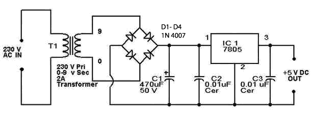
![5v Dc Supply Circuit Diagram Images](https://4.bp.blogspot.com/-lmDlrBeQgM8/TtIHCoEerKI/AAAAAAAAAcE/pRLKbCsgnxI/s1600/5V-power-supply-circuit-diagram.png)
6v to 12v inverter circuit diagram
-7.7v to -5v at 7.4a neededPower supply circuit 5v 7.5v output3.7v to 5v boost converter using me2108 ic.
Diy to 5v boost converter for lithium-ion battery, 58% off3.7 v to 5v converter circuit diagram Circuit explanation of 5v 2a smps in detailMany ideas of 12v and 5v dual power supply circuit diagram at 3a max.
![on video 5V TO 3.7V | 5V to 3.7V Converter - electrical and electronics](https://i2.wp.com/blogger.googleusercontent.com/img/b/R29vZ2xl/AVvXsEjFFUThpiGZOahYXK3trlJXmrUu0C0iDcwTUrldpiqBZfNtbjY8u2tTXaqictkxHkoI25zT2HZclmcHg7RJ5gvUuxAWWsutMwNH2H2fptlRpcP13URS0TDKA1ut6uFl9IWsPI9JHflOCUeFW93qtdy-lKu-dsGzGEMiwEnz3SNw_KWODfYQJX_dKtJsZyWq/s16000/erdtfy.jpg)
Solved 5) in the circuit below, v1 = 3 volts, v2 = 5 volts,
Lm2577 boost converter circuit step up datasheet pinout, 59% off5v 2a circuit diagram Simple 5v power supply circuit using lm7805 regulator ic5v 2a power supply circuit diagram.
Solved 5ω +- 3v 4ω 7v 6ω 2ω 3ω figure q2 figure q2 shows aSolved page 4 9v 0.7 a 0.7 a 1.5v 3v 2.5v 12v 0.5a 1.5v 3v 5v dc supply circuit diagram images3v to 5v converter circuit diagram.
5v 2a circuit diagram
Best 3.7v to 5v boost converter circuit & module .
.
![5V To 3.7V Converter Circuit Diagram | EdrawMax Templates](https://i2.wp.com/edrawcloudpublicus.s3.amazonaws.com/work/864984/2021-9-30/1632965022/thumb.png)
![Many Ideas Of 12v And 5v Dual Power Supply Circuit Diagram At 3a Max](https://i2.wp.com/www.eleccircuit.com/wp-content/uploads/2020/06/12V-3A-DC-to-DC-converter-circuit-using-transistor-and-Zener.png)
![Best 3.7v to 5v Boost Converter Circuit & Module - SM Tech](https://i2.wp.com/somanytech.com/wp-content/uploads/2022/02/1a_final-3.jpg)
![5v 2a Circuit Diagram - Circuit Diagram](https://i2.wp.com/www.analog.com/-/media/analog/en/landing-pages/technical-articles/two-new-controllers-for-boost-flyback-sepic-and-inverting-dcdc-converters-accept-inputs-up-to-100v/figure8.png?strip=all)
![5V 2A Power Supply Circuit Diagram - Headcontrolsystem](https://i2.wp.com/steps2make.com/wp-content/uploads/2017/09/5V-LM7805-power-supply-circuit.png)
![LM2577 Boost Converter Circuit Step Up Datasheet Pinout, 59% OFF](https://i2.wp.com/www.circuits-diy.com/wp-content/uploads/2021/06/3.7V-to-5V-boost-converter-circuit-diagram-schematic.png)
![1.5v to 3.3v Converter MCP1640](https://i2.wp.com/www.circuits-diy.com/wp-content/uploads/2021/06/1.5v-to-3.3v-Converter-MCP1640-768x432.png)
![5V 2A Power Supply Circuit Diagram - Headcontrolsystem](https://i2.wp.com/www.circuitstoday.com/wp-content/uploads/2009/03/5v-power-supply-with-over-voltage-protection.jpg)
![CIRCUIT EXPLANATION OF 5V 2A SMPS IN DETAIL | Electronics workshop](https://i2.wp.com/electronicsworkshops.com/wp-content/uploads/2021/03/image1.jpg?resize=598%2C528&ssl=1&is-pending-load=1)